 By DSP Staff
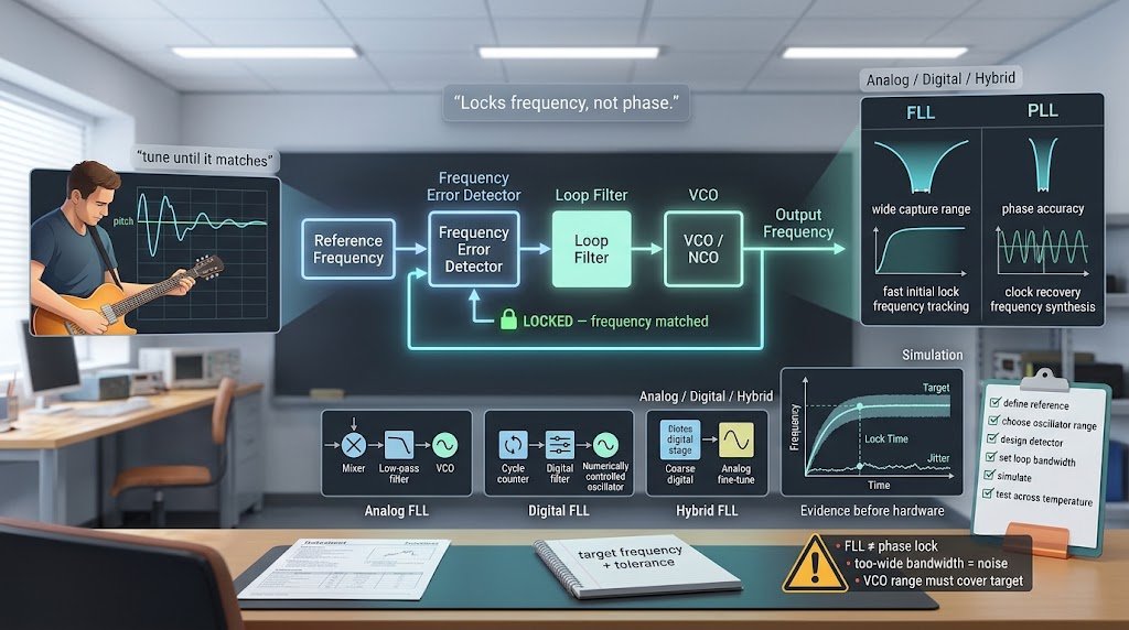
Table of Contents
- What Is a Frequency Locked Loop?
- Why Does a Frequency Locked Loop Matter?
- Frequency Locked Loop — Key Facts and Types
- How to Build and Use a Frequency Locked Loop
- Common Mistakes and Myths to Avoid
- Expert Tips for Best Results
- Frequently Asked Questions
Your phone, your Wi-Fi router, and your car radio all depend on circuits that keep one signal matched to another. A frequency locked loop is one of the simplest and most dependable ways to do that job. Many engineers reach for a frequency locked loop when they need a signal to track a target frequency quickly, even before the fine phase details settle.
This guide explains what a frequency locked loop is, how it differs from a phase locked loop, and where each one fits. You will see how the core blocks work, what a frequency error detector does, and how a digital frequency locked loop is built in software and hardware. You will also get a step-by-step method, common mistakes to avoid, and practical tips. By the end, you will know when an FLL is the right tool for your design.
What Is a Frequency Locked Loop?
A frequency locked loop (FLL) is a feedback control system that adjusts the frequency of an oscillator until it matches a reference frequency. Think of it like tuning a guitar string. You pluck the string, listen to the pitch, and turn the peg until the note matches the one you want. The FLL does the same thing automatically, but it checks the pitch thousands of times per second.
The loop has three basic parts. A frequency error detector compares the output frequency with the reference. A loop filter smooths that error into a steady control signal. A voltage-controlled oscillator (VCO) changes its output frequency in response to that signal. When the error drops to zero, the loop is locked.
An FLL cares only about frequency, not exact timing. That is its defining trait, and it is why the design is so forgiving.
Why Does a Frequency Locked Loop Matter?
Engineers choose an FLL because it solves specific problems cleanly. Here are the main benefits:
- Wide capture range: An FLL can pull in a signal even when it starts far from the target frequency. A PLL often needs the signal to be close first.
- Fast initial acquisition: The loop reaches lock quickly, which helps in burst communication and radio receivers.
- Simpler frequency tracking: When you only need the frequency right, you avoid the extra complexity of phase matching.
- Robust start-up: The FLL can recover after a sudden drift or power glitch without losing track of the signal.
- Good fit for digital systems: Digital versions run easily on microcontrollers and FPGAs.
- Lower design effort for frequency-only tasks: Fewer tuning parameters mean faster prototypes.
According to the IEEE Xplore digital library, frequency acquisition techniques remain a core topic in modern communication receiver research, which shows how much engineers still rely on these loops.
Frequency Locked Loop — Key Facts and Types
Before you pick a design, you should know how an FLL differs from its close cousin, the PLL. The table below summarizes the main contrasts.
| Feature | Frequency Locked Loop (FLL) | Phase Locked Loop (PLL) |
|---|---|---|
| Locks on | Frequency | Frequency and phase |
| Capture range | Wide | Narrower |
| Phase accuracy | Not controlled | Precisely controlled |
| Typical use | Frequency tracking, acquisition | Clock recovery, frequency synthesis |
| Complexity | Lower | Higher |
Analog Frequency Locked Loops
An analog FLL uses a frequency detector built from analog components, such as a mixer and a low-pass filter. The detector outputs a voltage that depends on how far the input is from the target. This voltage steers the VCO. Analog designs are fast and cheap, but they drift with temperature and component tolerance.
Digital Frequency Locked Loops
A digital frequency locked loop replaces analog blocks with counters, digital filters, and numerically controlled oscillators. The loop counts cycles over a fixed window and compares the count to the expected value. Digital versions are stable, repeatable, and easy to tune in code. They suit modern chips and embedded systems.
Hybrid Designs
Many real products combine both approaches. A coarse digital loop brings the frequency close, then an analog loop fine-tunes it. You get fast lock and clean output in one design.
How to Build and Use a Frequency Locked Loop
Follow these steps to design a working FLL for your project.
- Define your reference frequency. Write down the exact target frequency and the tolerance you can accept. This number drives every later choice.
- Choose your oscillator. Select a VCO or numerically controlled oscillator whose range covers your target with some margin. Check its gain and linearity from the datasheet.
- Build the frequency error detector. Use a mixer and low-pass filter for analog designs, or a cycle counter for digital ones. Make sure the output is zero when the frequency matches.
- Design the loop filter. Pick a filter bandwidth that is wide enough for fast lock but narrow enough to reject noise. A first-order low-pass filter is a good starting point.
- Simulate before you build. Run a simulation in a tool like MATLAB, Python, or SPICE. Watch the lock time and overshoot, then adjust the filter until the response looks right.
- Test on hardware and verify lock. Apply a real input, record the output frequency over time, and confirm it stays within your tolerance.
Common Mistakes and Myths to Avoid
Mistake: Assuming an FLL locks the phase too. An FLL aligns frequency only. If you need phase accuracy for clock recovery or synthesis, the truth is that you need a PLL.
Mistake: Setting the loop bandwidth too wide. A wide bandwidth locks fast but lets noise pass through. The truth is that you should balance speed against noise using simulation.
Mistake: Ignoring the VCO’s tuning range. A VCO that cannot reach your target frequency will never lock. The truth is that you must check the range before you design the filter.
Myth: Digital loops are always better than analog. Digital loops offer repeatability, but they add quantization noise and latency. The truth is that each approach suits different constraints.
Myth: A lock indicator proves the loop is working well. A lock flag only shows that the error is small. The truth is that you should measure output jitter and stability as well.
Expert Tips for Best Results
Start with a clear frequency spec. Write the target and tolerance before you touch any hardware, because vague specs lead to endless redesigns.
Leave headroom on the VCO. Choose an oscillator whose range covers your target with margin, so temperature changes do not push you out of lock.
Simulate noise, not just lock time. A loop that locks fast but jitters badly will fail in real systems.
Use a digital counter window carefully. Longer windows give better resolution but slower updates, so pick the window that matches your application.
Test across temperature. Run your final design hot and cold, since component drift can break an otherwise good loop.
Frequently Asked Questions
What is the difference between a frequency locked loop and a phase locked loop?
A frequency locked loop matches only the frequency of a signal, while a phase locked loop matches both frequency and phase. The FLL has a wider capture range and locks faster from a distant starting point. The PLL offers precise phase alignment, which clock recovery and frequency synthesis require. Choose the FLL when frequency is all you need, and the PLL when timing accuracy matters.
Can a frequency locked loop be built in Python?
Yes, you can simulate an FLL in Python using NumPy and SciPy. Model the VCO as an integrator, the error detector as a subtraction or cycle counter, and the loop filter as a discrete transfer function. Run the simulation, plot the frequency over time, and adjust gains until the output settles. This approach helps you test ideas before buying any hardware.
Where is a frequency locked loop used in real products?
Frequency locked loops appear in GPS receivers, software-defined radios, Wi-Fi and cellular modems, and motor speed controllers. They help these devices acquire and track a frequency quickly. Wireless systems rely on them during start-up, when the signal may drift. Many designs also pair an FLL with a PLL, using the FLL for fast acquisition and the PLL for precise tracking.
Conclusion
A frequency locked loop keeps an oscillator matched to a target frequency, and it does so with a wide capture range and fast lock. Remember three key points: an FLL locks frequency rather than phase, a frequency error detector drives the whole loop, and a digital frequency locked loop offers repeatable, software-friendly control. Choose between an FLL and a PLL based on whether you need phase accuracy.
Start today by writing down your target frequency and tolerance, then sketch a simple loop on paper. Try simulating it in Python this week, and you will understand the behavior faster than any diagram can show. Which application are you designing a frequency locked loop for, and what challenge are you facing? Share it in the comments below.